

You're staring at a stripped clock mechanism on a clean white sheet, and the first tooth already looks wrong. The hub feels too large, the circles don't share a centre, and you're wondering whether a portfolio drawing of gears needs to look like a machine drawing or an artwork.
The answer is both, but not all at once. A strong study begins with observation, construction, and proportion. It can then develop into a thoughtful page about time, industry, repetition, labour, or the relationship between the human body and machines. For Level 2 and Level 3 creative students, that combination makes gear studies useful evidence of both technical control and personal enquiry.
Table of Contents
- Why Gear Drawings Belong in an Art and Design Portfolio
- Breaking Down the Basic Geometry of a Gear
- Plotting Teeth Around the Pitch Circle
- Choosing Flat, Perspective, and Section Views
- Drawing Gears as a Working Assembly
- Common Mistakes That Cost Portfolio Marks
- Using Gear Studies in a UK Progression Portfolio
Why Gear Drawings Belong in an Art and Design Portfolio
A gear is an excellent subject because it refuses to become convincing through decoration alone. Its teeth must repeat, its circles must share a centre, and its thickness must remain believable when you turn the object in space. Those demands test accurate observation of complex geometry, sustained concentration, and the ability to translate engineering precision into a drawn mark.
That's why gear drawings aren't reserved for product design applicants. Fine art, illustration, animation, and graphic communication tutors can also respond to mechanical subject matter because it shows intellectual curiosity beyond the life model or familiar still life. A student who studies a clock mechanism carefully is showing interest in how objects work, how they're made, and how visual systems create meaning.
Begin with the object, not the symbol
A common weak drawing starts with a remembered symbol for a gear, usually a flat star shape with evenly pointed teeth. It may be recognisable, but it doesn't demonstrate much looking. A better study records the particular object in front of you, including worn edges, grease marks, different metal surfaces, openings, fasteners, and the way light disappears between the teeth.
Gears appear frequently in Level 2 and Level 3 progression portfolios because they offer a useful degree of challenge. They're ambitious enough to reveal care, yet achievable with measuring, construction lines, and patient revision. If you're working from a photograph, a tool that can simplify photos into outlines may help you identify the main contours before you return to the reference and add observed detail. Use it as a starting aid, not as a substitute for judgement.
Portfolio principle: Tutors want to see how you looked, measured, tested, and refined. They aren't only judging the final dark outline.
The following decisions matter: which circles you construct, how you divide the teeth, and whether a flat, perspective, or section view best communicates your idea. A drawing can be visually attractive and still feel uncertain if those choices happen by guesswork. Treat the page as evidence of thought, not merely a finished illustration.
Breaking Down the Basic Geometry of a Gear
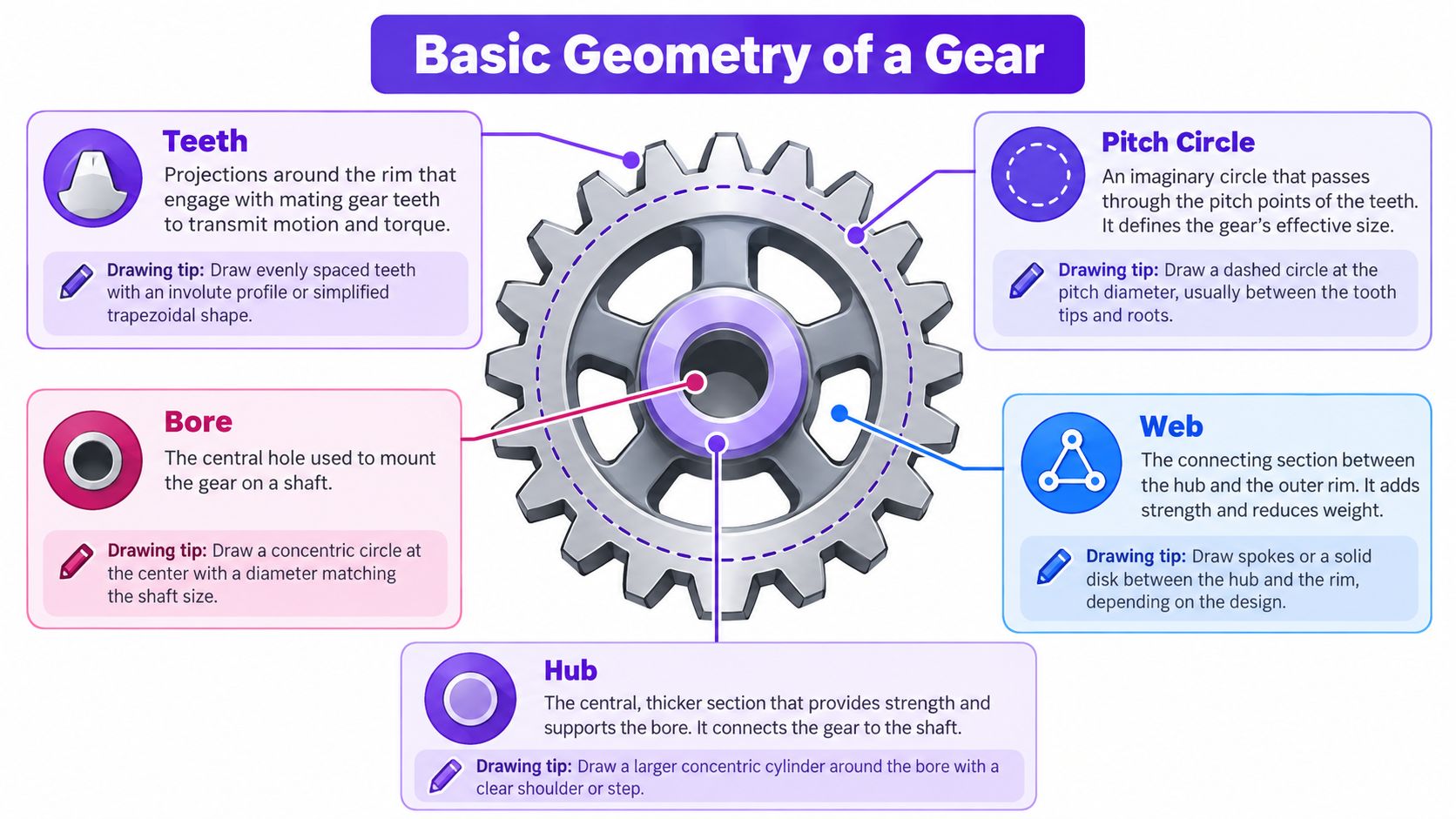
Don't approach a gear as one complicated silhouette. Treat it as a set of related structures, each with its own purpose and construction line. This makes the drawing easier to control and gives the viewer a clearer sense that you understand the object.
Build from the centre outward
Start by locating the centre of the gear. The bore is the axle hole, while the hub is the raised central section around it. Between the hub and the toothed rim sits the web, which may be solid or shaped with openings. These parts have different thicknesses and catch light differently, so separating them helps you avoid a flat result.
The pitch circle is an imaginary circle positioned through the working region of the teeth, where one gear meshes with another. You usually won't draw it as a heavy finished contour, but it's essential during construction. The addendum describes the tooth height above the pitch circle, and the dedendum describes the depth below it. The root circle marks the base of the spaces between teeth.
Use a real gear, a clock mechanism, or a clear printed reference. A pair of dividers, callipers, a ruler, and a compass can help you compare the bore, hub, web, and outer diameter. You don't need to copy every measurement as a manufacturing specification. Instead, record the relationships. If the bore occupies a particular fraction of the hub, preserve that relationship on the page.
Let the guidelines remain useful
Light pencil circles aren't evidence of failure. They show how you solved the problem. Keep them visible in a preparatory study, or photograph the page before you strengthen the final lines. A portfolio assessor can then see the reasoning behind the result.
You can develop this approach alongside drawing in construction, especially when practising how overlapping forms, axes, and measured proportions support a convincing object study. Avoid pressing hard too soon. Heavy construction makes corrections difficult and can turn a carefully observed gear into a muddy graphic shape.
The most revealing mistake is treating the gear as a flat star. That choice removes the pitch logic, depth, and internal structure. Once the separate circles are secure, the next task is to distribute the teeth evenly around the pitch circle.
Plotting Teeth Around the Pitch Circle
Equal spacing is what makes a gear read as a mechanical object rather than a decorative cog. You can draw beautiful shading, but irregular teeth will still make the object feel unreliable. Plot the positions first, then draw the tooth forms.
A practical construction method
Draw the pitch circle lightly. Add the outer addendum circle and the root circle if your reference allows you to identify them. Keep all three centred on the same point.
Count the teeth. Your reference determines the number. Don't estimate this from a small photograph if you can enlarge the image or examine the object directly.
Divide the full circle. Calculate the angular pitch by dividing 360 degrees by the tooth count. A protractor provides a direct method. You can also halve angles repeatedly when the division suits that construction method.
Mark the tooth centres. Place a small, light tick at each calculated position on the pitch circle. These marks act as a map for the tooth profiles.
Construct each tooth outward and inward. Extend the tooth towards the addendum circle, then shape the gap down towards the dedendum and root circle. Observe the reference closely. The tooth tip, flank, and root aren't always represented by simple triangles.
Check the rhythm. Look for consistent tooth width and gap width before darkening anything. Rotate the page, step away from it, or use a mirror to expose uneven spacing.
Practical rule: Don't correct individual teeth in isolation. Check the pattern around the complete circle, because a local adjustment can make the opposite side feel uneven.
The most common reason a gear drawing loses credibility is not a lack of shading. It's inconsistent spacing. If one tooth is broad and the next gap is narrow, the viewer notices the error even when they can't explain it technically.
Work from light marks to firm marks. You might use a harder pencil for circles and a softer pencil for the final edge, but line weight should follow structure. A hidden construction circle can remain delicate, while a visible tooth edge deserves more emphasis.
The plotting process should eventually disappear into the finished image. That isn't wasted effort. Invisible preparation is what allows the final drawing to look calm, balanced, and almost effortless.
Choosing Flat, Perspective, and Section Views
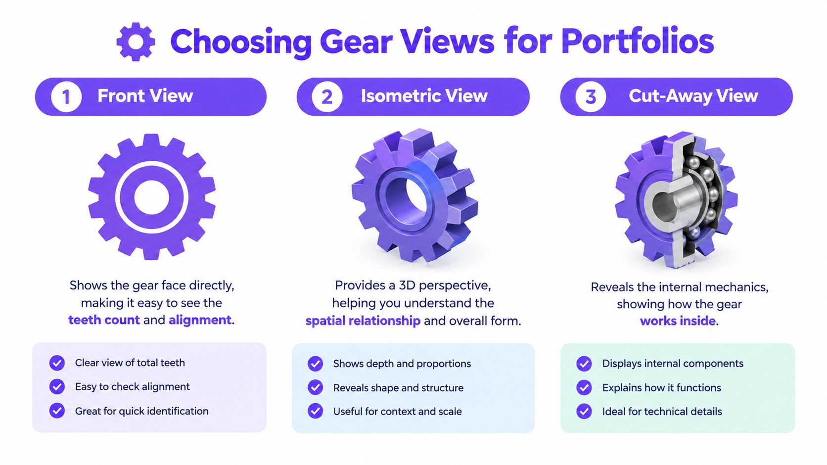
A front view, an isometric view, and a cut-away view answer different questions. Choosing between them is less about showing every possible detail and more about deciding what you want the portfolio page to communicate.
Match the view to the evidence
| View | What it demonstrates | Useful portfolio purpose |
|---|---|---|
| Front view | Tooth count, concentric circles, and alignment | Measured observation |
| Isometric view | Hub depth, web thickness, and shaft direction | Spatial reasoning |
| Cut-away view | Bore, keyway, root, and internal construction | Analytical understanding |
The flat front view gives you the clearest test of accuracy. It shows whether the teeth are distributed properly and whether the pitch circle sits in the correct relationship to the outer edge. Choose it when the page needs to prove careful measurement.
An isometric view, often built around a 30 or 45 degree angle, reveals thickness and direction. The hub becomes a cylindrical form, the web gains depth, and the shaft can travel through the centre. The circles on the front face become ellipses, not unchanged circles. Practise this transformation through a wider exercise such as drawing a sphere, because observing curved forms helps you understand how an angle changes the appearance of a surface.
Use the section view to show thinking
A cut-away drawing can reveal the bore, keyway, shaft, tooth root, and layered construction. It signals that you're asking how the object operates, not just how it looks from outside. This can support a narrative about industrial heritage, repair, or the hidden mechanisms inside familiar objects.
For a modern mechanism brief, an isometric assembly may communicate invention and movement more effectively. For a study about time, a cut-away clock gear can make the concealed system central to the idea. You don't have to choose one view for the entire page. A study sheet can combine a large front view with a smaller isometric or section view, provided each drawing has a clear label.
Keep the scale consistent where views are meant to relate. Tutors often notice scale shifts before they notice minor rendering weaknesses. Label the view, note whether it's observed or constructed, and explain any cut line. Deliberate annotation makes the page feel organised rather than accidental.
Drawing Gears as a Working Assembly
An isolated gear proves that you can study one object. A working assembly proves that you understand relationships between objects. Two meshing gears require accurate centres, compatible spacing, and a believable sense of movement.

Begin with the larger driver gear. Establish its centre, pitch circle, outer form, and thickness before adding the second gear. The centre distance must come from the reference or from a proper gear relationship, using the module or a measured tooth pitch where that information is available. Don't place the second circle by eye and hope the teeth meet.
Plot the second pitch circle at the exact required distance. Check the point where the pitch circles meet, then examine the tooth and gap relationship. The teeth should interlock without floating, overlapping impossibly, or losing their depth at the contact point.
Add the surrounding mechanism
Once the gears work geometrically, draw the parts that make the assembly believable:
- Shaft lines: Carry each centre through the hub and show the direction of the axle.
- Bearings: Use them to establish how the shafts sit inside a frame.
- Supporting frame: Give the gears a physical context instead of leaving them suspended on the page.
- Engaged flanks: Shade opposite tooth faces consistently to suggest contact and rotation.
- Inset construction: Include a small diagram of the pitch circles and centre distance to reveal your process.
The assembly earns more attention than a collection of unrelated cogs because it demonstrates interaction. It also gives you opportunities to vary line weight, texture, and tonal emphasis. Keep the contact area clear, though. If shading becomes too dark around the mesh, the viewer may lose the very relationship you intended to show.
A strong page might place the finished assembly at the centre, with a measured front view, a partial construction diagram, and a detail of the tooth contact nearby. That arrangement turns technical drawing into visual investigation. It tells the assessor that you can move from observation to analysis without abandoning visual sensitivity.
Common Mistakes That Cost Portfolio Marks
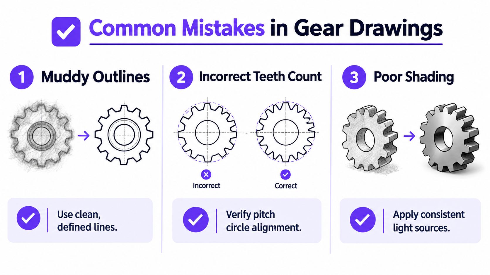
Mechanical drawings often lose quality through small decisions repeated across the page. A student may spend hours rendering metal, then discover that the teeth don't align or the hub face has been drawn as a circle in perspective.
Feedback that comes up repeatedly
Muddy outlines usually develop when the student redraws the same silhouette until it becomes dark and uncertain. Use a clean final contour over lighter construction, and erase selectively rather than scrubbing the whole page.
Incorrect centre distances make meshing gears look as though they're floating. Establish both pitch circles before drawing the teeth. If the centres are guessed, no amount of shading will repair the assembly.
Perspective errors appear when a cylindrical hub is turned in space but its front face remains circular. In an angled view, that face becomes an ellipse. Check the axis and compare the visible depth on both sides.
Missing construction lines hide the thinking process. Keep faint circles, centre lines, and division marks in developmental pages, or photograph them before finishing the final version.
Tracing directly from a photograph creates another problem. It may produce a neat contour, but it removes evidence of measurement and judgement. If you use a photograph, make a separate first attempt, annotate what went wrong, and then produce a more resolved study. That sequence shows development, which is more valuable than a flawless but unexplained copy.
Before submission, ask a peer to check:
- Structure: Do the circles share a centre where they should?
- Spacing: Do the teeth and gaps repeat convincingly?
- Viewpoint: Are ellipses, shafts, and visible thickness consistent?
- Evidence: Can someone see how you constructed the form?
- Finish: Are the darkest marks reserved for important edges and contact points?
Using Gear Studies in a UK Progression Portfolio
At GCSE-equivalent Level 2, treat a gear drawing as an observational study. Show measuring, line control, tonal rendering, and a short annotation explaining what you noticed and changed. This foundation supports progression rather than trying to imitate a professional manufacturing document.
At A Level or Level 3, push the subject further. Combine mechanical studies with collage, print, photography, abstraction, or a conceptual theme such as industry, time, memory, or the human body. A gear can remain recognisable while becoming part of a more personal visual language.
For a Foundation Diploma or BTEC route, show sustained investigation through a sequence. Include an initial observation, construction experiments, a perspective or section study, an assembly, and a resolved interpretation. You don't need to fill a sketchbook with identical cogs. Three to five varied gear studies can be enough when each one develops a different question.
UK progression routes emphasise foundations and evidence. UAL states that applicants for its Level 3 International Introduction courses usually need education to at least Level 2, equivalent to GCSE study, and then submit a recent digital portfolio of no more than 20 pages containing work such as drawings, photographs, visual research, moving images, written work, or digital layouts. UAL's course guidance gives a useful sense of how varied that evidence can be.
For a university-ready portfolio, photograph work in even light, label the object and viewpoint, explain your decisions, and practise discussing what changed between studies. Guidance on how to make an online art portfolio can help you organise those pages so the gear studies sit within a clear progression rather than appearing as isolated exercises.
The Online College of Art & Design (OCAD) offers flexible, tutor-led Level 2 and Level 3 art and design courses with portfolio-centred coursework, feedback, and online studio resources. If you want structured support developing observational studies such as drawing of gears for university progression, visit The Online College of Art & Design (OCAD) to explore the available pathways.