

You've spent an evening drawing a building, chair or figure, but the result still looks flat. The outline seems tidy until the subject turns, overlaps itself or needs to sit convincingly in space. A window drifts out of alignment, a chair leg changes direction, or a figure's torso feels too short even though the outside contour looks carefully observed.
That frustration is common at Level 2 and Level 3. The problem usually isn't a lack of talent. It's that the drawing needs an underlying structure. Drawing in construction gives you that structure, helping you build complex subjects from simple forms before refining the surface. It also creates a useful bridge between creative observation and the precise communication expected in architecture, interior design and other built-environment subjects.
Table of Contents
- Introduction to Drawing in Construction and Why It Matters
- How Construction Drawing Builds Form From Basic Shapes
- A Practical Workflow for Constructing Any Subject
- Reading Scale Sections and Elevations Like a Pro
- Targeted Exercises Tips and Mistakes to Avoid
- Building Your Portfolio and Next Steps Toward University
Introduction to Drawing in Construction and Why It Matters
A student working from a still-life arrangement might begin with the outer edge of a ceramic vase. The contour can look accurate from one viewpoint, yet the neck may not feel centred over the body, and the opening may appear pasted on rather than turned in space. Adding more shading rarely fixes the problem because the drawing's internal structure was never established.
Construction drawing approaches the same vase differently. You might begin with a tall cylinder, place an ellipse at the rim, mark a central axis and then adjust the profile around that volume. The visible outline becomes the final result of a three-dimensional decision, not a guessed boundary.

Construction is more than an outline
An outline records where a subject appears to end. Construction records how the subject occupies space. You use boxes, cylinders, spheres, cones and other simple volumes to establish proportion, direction and depth. These forms can remain light and loose at first, then become increasingly specific as you understand the subject.
The method works for many portfolio subjects:
- Figures: A ribcage can begin as an oval volume, the pelvis as a box-like mass, and limbs as cylinders that follow an axis.
- Objects: A mug can be built from a cylinder, with an attached torus-like handle and ellipses indicating the opening and base.
- Buildings: Rooms, walls and roof masses can start as boxes, then develop into plans, elevations and sections.
- Organic subjects: A cat, plant or folded form can be simplified into overlapping volumes before you describe its distinctive surface.
This way of working helps you see through the subject. You're not drawing every visible edge at once. You're asking what sits behind the edge, which forms overlap, and how the central direction of each part changes.
Why universities value this thinking
A university portfolio needs more than attractive final images. It should show how you observe, test, correct and develop an idea. Construction studies make that thinking visible. A page showing several rough boxes, axis lines and proportion corrections can demonstrate stronger problem-solving than a single polished drawing with no evidence of development.
The same principle appears in professional drawing communication. UK construction drawing became formally standardised through British Standards during the twentieth century, with BS 1192 becoming a key code of practice for the production, format and standards of architectural, engineering and construction information. Educational material on UK construction drawing records that recognisable technical drawings appeared in the late eighteenth century, while the late twentieth century brought the transition from manual origination to CAD, with standards including BS 308 and BS 1192 developing alongside that change. The language of drafting provides useful background for students who want to understand this history.
For a broader introduction to how architectural drawings communicate design information, the RBA Home Plans blueprint overview is a helpful companion. The key lesson is simple: construction drawing isn't a trick for making sketches look more realistic. It's a disciplined way to think, test form and communicate clearly.
How Construction Drawing Builds Form From Basic Shapes
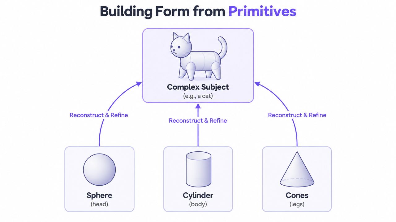
Construction drawing starts with a question: What simple volumes could explain this complex subject? A cat might be reduced to a sphere for the head, a cylinder for the body and cones or tapered forms for the legs. A building might become a group of boxes joined along clear axes. A human hand could begin as a block for the palm and smaller cylinders for the fingers.
Outline versus volume
Contour drawing follows the visible boundary. It can be sensitive and expressive, but it becomes unreliable when the subject turns away from you or when one form passes behind another. If you draw a seated figure only by tracing edges, you may lose the connection between the shoulders, spine, pelvis and legs.
Volumetric construction gives you a hidden framework. Light centre lines show the direction of a cylinder or the tilt of a head. Cross-contour lines wrap around a form, just as horizontal lines might wrap around a tin. These marks tell you whether the form is facing towards you, turning away or leaning through space.
A sphere doesn't need a detailed surface to communicate its position. A curved centre line and an elliptical cross-contour can show its rotation. A box can establish the angle of a building corner before you add windows, doors or materials.
A reliable mental model
Work from large to small. First identify the dominant mass, then attach secondary forms, then refine the transitions. For a vase, the dominant mass might be a cylinder or a softened cone. For a figure, it might be the combined relationship between the ribcage and pelvis. For a small building, it could be the main rectangular block and the roof volume.
Ask yourself:
- Where is the main axis? Mark the direction that controls the form.
- What is the simplest volume? Choose a box, cylinder, sphere or cone before adding irregular edges.
- Which forms overlap? Decide what sits in front and what passes behind.
- How do cross-contours behave? Their curves should follow the surface and change with perspective.
- What must stay consistent? Check that attached forms share the same perspective and proportion system.
Construction doesn't mean every subject must look mechanical. You can keep the final line expressive while using a structural scaffold underneath. Students moving towards architecture can compare this approach with the spatial clarity required in a professional floor plans guide, where relationships between rooms matter more than decorative surface.
If spheres feel difficult, practise the drawing a sphere tutorial and focus on the axis and cross-contours rather than shading. Once you can turn a simple form convincingly, you can combine it with other forms to explain almost any subject.
A Practical Workflow for Constructing Any Subject
Start with the whole subject, not the most interesting detail. Before drawing a window frame, hand or facial feature, study the overall movement and outer envelope. The envelope is a loose boundary that contains the subject's largest height, width and directional changes.
For a seated mannequin, you might draw a light line showing the spine's movement, then a loose envelope around the head, torso, knees and feet. For a building, the envelope could indicate the main footprint and roof silhouette. This first pass prevents you from placing small parts accurately inside an incorrect overall shape.
Establish the main masses
Replace the loose envelope with simple forms. Use a box for a book, a cylinder for a mug, a sphere for a joint or a tapered box for a torso. Keep your lines light enough to change. At this stage, accuracy comes from relationships rather than detail.
Compare height and width. Check the size of one form against another. If the head appears too large in relation to the torso, correct the construction now rather than trying to disguise the error with hair or clothing.
Practical rule: If the subject doesn't read clearly as simple volumes, detail won't make the drawing structurally stronger.
Place axes and perspective
Give each major volume a direction. A cylinder needs an axis running through its centre, and its ellipses should respond to that axis and viewpoint. A box needs edges that agree with the same perspective system. On a building, mark the main horizontal and vertical directions before adding openings.
Use sighting to compare angles. Hold your pencil vertically or horizontally at arm's length, close one eye if that helps, and compare the angle you see with the angle on your page. This isn't about tracing. It's a way to check whether your observation and construction agree.
Look for alignment points. Does the vase rim sit over the base? Do the front and rear legs of a chair attach to the same seat volume? Do windows follow the face of the building rather than remaining flat against the paper?
Add cross-sections and intersections
Cross-sections explain how forms turn. Draw a few lightly across a cylinder, sphere or irregular mass. On a figure, a centre line through the ribcage can show the torso's rotation. On a building, a sectional cut can reveal floor levels, roof thickness and the relationship between rooms.
Intersections deserve attention. A handle joins a mug, a leg enters a torso, and a roof meets a wall. Don't draw both outlines until they collide. Show which form is in front, allow the attached form to follow the surface, and check whether the junction has a believable angle.
Refine without losing the framework
Once the large forms work, refine the contour. Vary line weight to separate foreground edges from lighter construction marks, and erase only the scaffolding that distracts from the final reading. Keep some process lines visible if they help explain how you solved the subject.
Details should respond to the underlying volume. A brick pattern on a curved wall should follow the wall's direction. Buttons on a jacket should sit across the torso's turning surface. Window openings should align with the building's planes and levels.
Finish with a comparison check:
- Proportion: Are the major height and width relationships still correct?
- Alignment: Do repeated elements share sensible axes?
- Depth: Do overlaps clearly show what is near and what is behind?
- Consistency: Do plans, elevations or views describe the same object?
- Editing: Have you removed marks that confuse the structure?
For portfolio work, photograph or scan several stages rather than only the final sheet. A sequence from gesture to block-in to refinement gives a tutor or university assessor evidence of decisions, corrections and visual reasoning.
Reading Scale Sections and Elevations Like a Pro
Creative students often understand scale emotionally before they understand it technically. A small sketch can suggest a large building, but a technical drawing must tell the reader exactly how the paper relates to the object. In UK construction drawing practice, dimensions are typically given in millimetres unless another unit is stated, and the drawing should show its scale clearly.
At 1:50, one millimetre on paper represents fifty millimetres in reality. At 1:100, one millimetre represents one hundred millimetres. The relationship is direct, but you should trust written dimensions rather than measuring the paper, because printing, paper shrinkage and distortion can introduce error. UK architectural drawing guidance on scale explains this practical distinction.
Common UK drawing scales
| Scale | Typical Use | What It Shows |
|---|---|---|
| 1:50 | Floor plans, sections and elevations | More construction and room detail |
| 1:100 | Whole-building plans and planning submissions | General arrangement and key openings |
| 1:200 | Large buildings and site context | Wider relationships with less detail |
| 1:500 | Site plans | Building position and surrounding site information |
| 1:1250 | Location plans | Broader site and location context |
A scale bar supports the written scale and gives the viewer a visual check. Include figured dimensions as well. A drawing marked “Not to scale” won't provide the same useful communication as a properly scaled drawing with dimensions and a scale bar.
Elevations show the outside
An elevation is a vertical view of one face of a building. It communicates external height, openings, roof shape, materials and the relationship between visible elements. If you're drawing a house elevation, windows should line up with the plan and their vertical positions should agree with the section.
Don't treat an elevation as a decorative front view. It's an orthographic drawing, so the information needs to remain measured and consistent. For a portfolio, a carefully annotated elevation can show that you understand how a flat representation describes a three-dimensional form.
Sections reveal the inside
A section is made by imagining a vertical cut through a building. It reveals internal space and relationships that an elevation can't show, including floor levels, roof intersections, wall build-ups and the way openings pass through the structure. UK planning guidance commonly distinguishes sections from elevations and expects the scale to be legible, often 1:100 or 1:50. Thurrock Council's guidance on elevations and sections gives a clear example of this expectation.
A plan explains horizontal relationships. An elevation explains an outside face. A section explains what happens through the building.
Keep your plan, elevation and section coordinated. If a window appears at a particular location in plan, it should occupy a compatible position in the elevation and section. This cross-check is excellent portfolio evidence because it demonstrates that you can communicate one design through several drawing types.
For visual context on how finished project information can be recorded and presented, architectural photography for contractors can help you study the relationship between drawings, built surfaces and construction detail.
Targeted Exercises Tips and Mistakes to Avoid
Construction improves faster when each exercise isolates a specific decision. Instead of drawing a complete building every day, practise the parts that make a complete drawing reliable. Keep the studies on the same page or in a process sketchbook so your development remains visible.
Build a small drill routine
Begin with primitive stacking. Draw spheres, cylinders and boxes touching, overlapping and passing behind one another. Focus on the order of forms. If a cylinder enters a box, show the junction rather than allowing both outlines to float independently.
Follow with cylinder rotation. Draw the same can, pipe or mug from different viewpoints. Change the ellipse openings and central axis while keeping the object's proportions stable. This develops the ability to turn forms instead of repeating a symbol for “cylinder”.
Use two-point perspective boxes for buildings, furniture and packaging. Place the box first, then add doors, windows or panels to its planes. If the details don't follow the box, the drawing will flatten.
Finish with subject breakdown. Take a reference photograph and write the simple forms beside it. A figure might become a sphere, two tapered masses and cylinders. A plant pot might become a cylinder with leaves arranged along directional arcs.
For observational figure work, life class drawing practice can help you focus on gesture, weight and proportion while applying the same construction logic.
Correct the errors early
Flattening forms usually happens when you draw only the outside contour. Add an axis and cross-contours, then check whether the curves describe the turning surface.
Starting with detail makes proportion errors harder to repair. Cover the detailed area with a sheet of paper or return to a fresh page and block in the largest masses first.
Inconsistent perspective appears when parallel edges point in unrelated directions. Revisit the main box or plane and redraw the attached details in relation to it.
Heavy construction lines can make revision feel impossible. Use a lighter touch, a softer pencil or a separate layer if you're working digitally. The first marks are decisions, not commitments.
Disconnected intersections make forms appear assembled from stickers. Draw through the junction, identify the overlap and adjust the contour so the parts share a believable structure.
Turn exercises into portfolio evidence
Don't discard every rough study. Select pages that show a clear question, such as how a cylinder turns or how a roof meets a wall, followed by a more resolved application. Add brief annotations about what changed and why.
A strong process page might include a reference, primitive studies, a failed attempt, a correction and a final drawing. That sequence demonstrates reflection without needing a long written explanation. It also gives you material to discuss in an interview or personal statement.
Building Your Portfolio and Next Steps Toward University
Construction belongs in a university portfolio because it shows how you think through form. Include exploratory pages, proportion checks, orthographic drawings and refined outcomes rather than presenting only finished illustrations. Your strongest sequence may move from a simple volume study to a designed object, room or building with plans, elevations and a section.
The UK Department for Education's school design and construction guidance refers to standardised designs with drawings and supporting information that demonstrate compliance with employer's requirements. That document-driven approach matters for creative applicants because it shows why drawings need to respond to a brief, including use, accessibility and spatial arrangement, rather than functioning as isolated images.
Scottish Qualifications Authority materials also identify introductory construction drawing outcomes such as recognising features and critical levels from a cross-section and working with a range of construction drawings. The SQA construction drawing specification gives you a useful checklist for checking whether your portfolio shows measured interpretation as well as visual confidence.
Before submitting work, ask:
- Process: Can a viewer see how the idea developed?
- Consistency: Do your plan, elevation and section describe the same design?
- Accuracy: Are scale, dimensions, labels and levels clear?
- Reflection: Have you explained what you corrected?
- Range: Does the portfolio include both observational and designed work?
You can also extend your visual language through soft pastel drawing, especially when you want to contrast precise construction studies with material, colour and atmospheric experiments. Keep returning to basic forms. They'll support architecture, illustration, interior design, product design and wider construction literacy.
The Online College of Art & Design (OCAD) offers flexible, tutor-led courses from Level 2 through Level 3 and foundation pathways, with online studio units, assignments, video tutorials and portfolio workspace. Visit The Online College of Art & Design (OCAD) to explore a structured route for developing construction drawing, receiving feedback and preparing creative work for university.